

Introduction
A semi trailer wiring diagram is a schematic representation of the electrical circuits connecting the tractor to the trailer through a standardized connector, typically a 7-pin plug. For maintenance technicians and fleet managers, the diagram is not merely a reference document—it is the primary diagnostic tool for isolating faults in lighting, braking, and ABS circuits that, if neglected, can ground a trailer or create safety violations at inspection.
Electrical failures on semi trailers are rarely random. They develop through corrosion, vibration-induced fatigue, poor grounding, or improper repairs that introduce resistance into circuits designed for specific voltage drop limits . A technician who understands the wiring diagram can trace a symptom—dim lights, a persistent ABS warning, or intermittent turn signals—to its root cause rather than replacing components speculatively. This guide explains the standard 7-pin connector architecture, the function of each circuit, the most common failure modes, and the diagnostic approach that separates a lasting repair from a repeat comeback.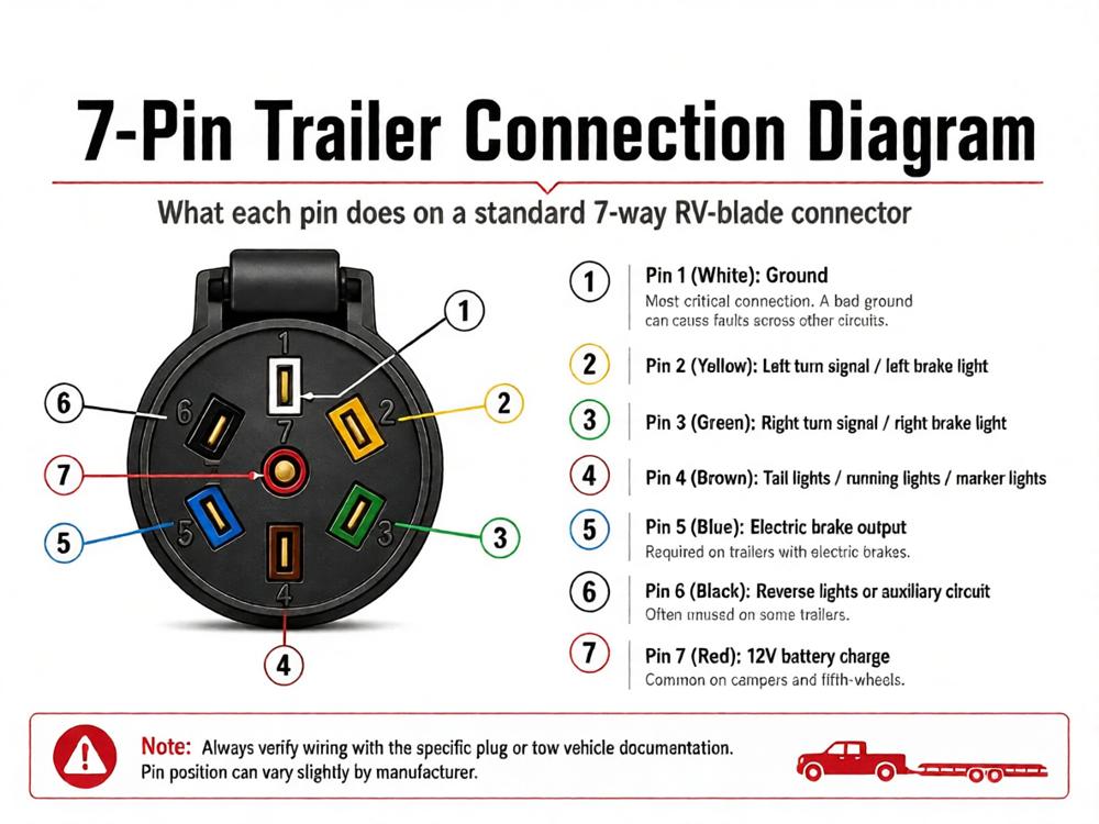
Core Powertrain and Structural Design
Connector Architecture: SAE J560 and ISO Standards
The semi trailer’s electrical interface is governed by regional standards. In North America, SAE J560 defines the 7-pin 12V connector used for primary trailer functions, including lighting and ABS power . The standard specifies pin assignments, wire gauge, and current capacity. A common SAE J560 pinout assigns Pin 1 (white, 8 AWG) as ground, Pin 2 (black) for clearance and side marker lamps, Pin 3 (yellow) for left turn and hazard, Pin 4 (red, 10 AWG) for stop lamps and ABS secondary power, Pin 5 (green) for right turn and hazard, Pin 6 (brown) for tail and license plate lamps, and Pin 7 (blue, 10 AWG) for continuous ABS primary power or auxiliary devices .
European trailers typically use a 24V system with 7-pin connectors conforming to ISO 1185 or ISO 3731, or a 15-pin ISO 12098 connector for advanced systems that require permanent power and CAN communication . The physical connector may appear similar, but voltage and pin functions differ—SAE J560 and ISO 1185 are not interchangeable without voltage conversion . A wiring diagram for any specific trailer must be verified against the connector actually installed, not assumed from regional convention.
Ground Circuit and Voltage Drop
The ground return is the most critical and most frequently compromised circuit in the trailer wiring system. Pin 1 carries the full return current for all lighting and auxiliary loads, and on SAE J560 connectors it uses 8 AWG wire specifically to minimize resistance . A ground connection that is mechanically present but electrically resistive—due to paint, corrosion, or loose hardware—produces symptoms that mimic multiple unrelated faults: lights backfeed through other circuits, markers glow faintly, and ABS modules throw intermittent codes .
Voltage drop testing is the definitive method for evaluating circuit integrity. A healthy lighting circuit should exhibit less than 0.5V drop between the source and the lamp terminal under load . Higher drop indicates excessive resistance at connectors, splices, or ground points. This measurement is more reliable than a simple continuity check, which can pass a circuit that fails under actual current draw.
ABS and Auxiliary Power Circuits
Pins 4 and 7 on the SAE J560 connector serve dual roles that reflect the evolution of trailer electronics. Pin 4 (red) provides stop lamp signal and ABS secondary power, while Pin 7 (blue) supplies continuous ABS primary power . The ABS system requires stable voltage to operate its ECU and wheel speed sensors; low supply voltage is a common fault code trigger on EBS-equipped trailers . For trailers with electronic braking systems (EBS), the ISO 7638 connector—a separate 5-pin or 7-pin dedicated connector—provides power and CAN communication independent of the lighting harness . A complete wiring diagram for a modern trailer must account for both the lighting connector and the ABS/EBS interface.
Technical Specifications
The table below presents representative parameters for a standard SAE J560 7-pin semi trailer connector in North American service. Values are derived from published standards and should be verified against the specific connector and trailer configuration.
| Key Parameter | Typical Technical Specification | Operational Significance |
|---|---|---|
| Connector standard | SAE J560 (12V); ISO 1185/3731 (24V) | Determines pin functions and voltage compatibility; standards are not interchangeable |
| Pin 1 (Ground) | White, 8 AWG; 40A continuous duty | Carries full return current; undersized or corroded ground causes multiple symptoms |
| Pin 4 (Stop/ABS secondary) | Red, 10 AWG; 40A continuous duty | Stop lamp signal and ABS backup power; critical for braking safety |
| Pin 7 (ABS primary/Aux) | Blue, 10 AWG; 40A continuous duty | Continuous ABS power or auxiliary device supply |
| System voltage | 12V nominal (SAE); 24V nominal (ISO) | Voltage drop limits and lamp compatibility depend on system voltage |
| Voltage drop limit (lighting) | ≤0.5V under load | Exceeding limit indicates resistance in circuit; causes dim lights and module faults |
| Insulation resistance | ≥1 MΩ at 500V DC | Verifies harness integrity; low resistance indicates moisture or damaged insulation |
| ABS warning lamp test | ON at key-on, OFF after ~2 seconds | Confirms ABS ECU self-test and communication; persistent ON indicates fault |
Comparative Advantages TCO and ROI
The alternative to a disciplined wiring diagnostic approach is parts substitution—replacing lamps, connectors, or harness sections based on symptoms rather than measurements. This approach appears cheaper initially because it avoids diagnostic labor, but it produces repeat failures when the root cause (typically a ground or voltage drop issue) remains unaddressed.
The cost impact of electrical failures varies by fault type. A lighting circuit open may cause 1–2 hours of downtime; a CAN bus fault on an EBS-equipped trailer can require 4–8 hours of diagnosis and repair; a power distribution fault may consume 8–16 hours . For a fleet operating on tight delivery schedules, a single misdiagnosed ground fault that recurs three times can exceed the cost of a proper diagnostic session by a wide margin.
A defensible comparison requires stated assumptions. Consider a fleet with 30 trailers, each experiencing two electrical repair events per year. If the average event costs 800 CNY in labor and parts, annual electrical repair cost is 48,000 CNY. If a structured diagnostic program—including voltage drop testing and technician training on the wiring diagram—reduces event frequency by 30% and eliminates repeat repairs on the same fault, the annual saving is approximately 14,400 CNY, against a training and tooling investment that may be recovered within the first year. The calculation excludes downtime costs, which typically exceed the repair invoice for revenue-generating trailers.
Repair versus replace decisions also affect cost. Industry practice guidance recommends replacing rather than repairing 10-gauge or larger wires and harnesses, because splices in high-current circuits introduce resistance and potential failure points . A splice that saves 50 CNY in parts may cost several hundred CNY in repeat labor and downtime if it fails under load.
Heavy Duty Application Scenarios
-
General freight and dry van operations: The standard 7-pin lighting circuit is the primary electrical system. Failure points cluster at the nose box connector, where the pigtail is exposed to road spray and mechanical strain, and at ground connections on the chassis frame . Regular inspection of the connector seal and ground strap condition prevents the most common faults.
-
Container drayage and port operations: High-frequency coupling and uncoupling accelerate wear on the 7-pin plug and receptacle. The connector’s strain relief and pin alignment should be checked at every PM interval. Trailer ABS power (Pin 7) must remain stable through the duty cycle to avoid fault codes that can trigger derates or inspection failures.
-
Heavy-haul and lowbed operations: Trailers with hydraulic gooseneck systems and multi-axle configurations often require auxiliary power circuits beyond the standard lighting harness. The wiring diagram for these trailers includes control circuits for hydraulic valves, axle lift, and steering systems, and may use the ISO 12098 15-pin connector for higher current capacity and CAN communication .
-
Refrigerated and specialized trailers: Reefer units, lift gates, and telematics devices draw auxiliary power through the connector or a dedicated circuit. The wiring diagram must account for these loads when sizing fuses and verifying voltage drop, because a circuit that performs adequately for lighting may fail under the continuous draw of a refrigeration unit.
Selection and Maintenance Considerations
Wiring diagram interpretation begins with verifying the connector standard installed on the trailer. A diagram for SAE J560 will not correctly describe an ISO 1185 system, and mixing the two can damage lamps or electronic modules. The diagram should be treated as a living document—updated when repairs modify routing or add circuits—rather than a manufacturer reference that is never consulted after initial delivery.
Key maintenance and diagnostic practices include:
-
Start with power and ground integrity. Before tracing individual circuits, verify that the tractor is supplying correct voltage at the connector and that the ground return has low resistance. A clean, paint-free chassis ground point is the foundation of all downstream diagnostics .
-
Use voltage drop testing, not just continuity. A circuit can show continuity and still fail under load. Measure voltage drop across connectors, splices, and ground paths while the circuit is energized. Limits of ≤0.5V for lighting circuits provide a pass/fail criterion .
-
Protect harness routing at flex points. The harness between the nose box and the chassis, and near axle and suspension movement areas, is vulnerable to fatigue. Flexible spiral protection, adequate slack, and secure attachment prevent conductor breakage and insulation chafing .
-
Seal connectors and splices. Moisture ingress is a leading cause of corrosion and intermittent faults. Automotive-grade sealed connectors with positive latches and dielectric grease on terminals improve reliability in wet and salted-road environments .
-
Document repairs and verify function. After any repair, reconnect the trailer, test all lighting and signaling functions, conduct an ABS self-test, and confirm voltage at rear lamps is within specification . A repair that “works in the yard” but fails under vibration or moisture has not been completed.
Conclusion
A semi trailer wiring diagram is only as useful as the technician’s ability to read it accurately and test against it systematically. The standard 7-pin connector, whether SAE J560 or ISO 1185, defines a circuit architecture in which ground integrity and voltage stability determine the reliability of every downstream function. Lighting faults, ABS warnings, and intermittent failures that appear unrelated often trace to a common cause: resistance in a ground path, a splice that should have been a replacement, or a connector that lost its seal.
The commercial case for disciplined electrical maintenance is straightforward. Electrical faults are among the most time-consuming to diagnose when approached without a diagram and a measurement plan, and among the most preventable when approached with both. Fleets that train technicians on voltage drop testing, maintain connector and harness protection standards, and document repairs consistently achieve lower electrical downtime and fewer repeat failures than those that treat wiring as a secondary concern. The diagram provides the map; the discipline provides the result.