

Introduction
A 7-way semi trailer plug wiring diagram depicts the electrical interface between a tractor and trailer under the SAE J560 standard, the North American specification for 12-volt heavy-duty trailer connectors introduced in 1951 and most recently revised in 2020 . This connector carries lighting signals, ground return, and continuous ABS power—functions that are legally mandated and safety-critical. Unlike the 7-way blade connector used on light-duty pickups and RVs, the SAE J560 round pin connector separates stop lamp and turn signal circuits, uses heavier wire gauges for higher current loads, and does not control the trailer’s pneumatic brakes directly .
The practical relevance of this diagram is diagnostic. Electrical faults on semi trailers are among the most time-consuming repair categories when approached without a systematic reference. A single corroded ground pin can cause multiple lights to flicker or dim simultaneously, sending a technician chasing individual lamp circuits that are functioning correctly . The wiring diagram provides the map: which pin drives which function, which wire gauge is specified, and where the common failure points lie.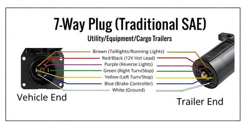
Core Powertrain and Structural Design
Engine and Transmission
The 7-way plug has no relationship to the tractor’s engine or transmission. Its power source is the tractor’s 12-volt electrical system, protected by fuses or circuit breakers in the tractor’s fuse panel. The connector’s pin 7 (blue) supplies continuous power to the trailer’s ABS ECU, a requirement under FMVSS 121 for heavy vehicles equipped with anti-lock braking systems . This continuous power allows the ABS to perform self-diagnostics and maintain readiness even when the trailer is stationary.
Hydraulic System
The SAE J560 connector does not control hydraulic systems. On trailers equipped with hydraulic functions—landing gear, lowbed gooseneck operation, or dump body lift—auxiliary power may be drawn through pin 7 or through a separate auxiliary connector (SAE J560 AUX type), which uses a different pin 1 layout and is marked yellow for identification . These auxiliary connectors are not interchangeable with the primary lighting connector.
Chassis and Structural Durability
The wiring harness routes from the trailer’s nose box through the chassis to the rear lighting and ABS components. Mechanical protection is the dominant durability factor. Harnesses must be secured away from suspension articulation points, sharp frame edges, and areas where road debris accumulates. Flexible spiral wrap at flex points and waterproof junction boxes at splice locations prevent the insulation damage and moisture intrusion that lead to conductor corrosion .
The connector itself is exposed to the most severe environment: road spray, salt, temperature cycling, and mechanical wear from repeated coupling. Pin corrosion is the most common connector fault, appearing as white or green powdery deposits that insulate the contact and block signal transmission . Regular cleaning and dielectric grease application at service intervals extends connector life significantly.
Technical Specifications
The table below presents the SAE J560 primary connector pinout as defined by the standard. Wire gauges reflect the minimum recommended cross-sections for 12-volt operation; actual harness specifications may vary by manufacturer.
| Pin | Function | Wire Color | Minimum Wire Gauge | Operational Significance |
|---|---|---|---|---|
| 1 | Ground return to towing vehicle | White | 8 AWG | Carries full return current; corrosion causes multiple simultaneous faults |
| 2 | Clearance, side marker, identification lamps | Black | 12 AWG | Marker lighting visibility; required for vehicle identification at night |
| 3 | Left turn signal and hazard lamps | Yellow | 12 AWG | Directional signaling; separate circuit from stop lamps |
| 4 | Stop lamps and ABS secondary power | Red | 10 AWG | Brake light signal; ABS backup power; heavier gauge for current capacity |
| 5 | Right turn signal and hazard lamps | Green | 12 AWG | Directional signaling; separate circuit from stop lamps |
| 6 | Tail lamps, license plate lamp, rear clearance | Brown | 12 AWG | Running light visibility; required whenever vehicle is in motion |
| 7 | Continuous ABS primary power / auxiliary devices | Blue | 10 AWG | ABS ECU power; loss triggers ABS warning and potential derate |
Comparative Advantages TCO and ROI
The alternative to the SAE J560 round-pin connector in light-duty applications is the 7-way blade connector used on pickup trucks and recreational trailers. The blade connector combines stop and turn signals on the same pins, uses lighter wire gauges, and is physically incompatible with the SAE J560 round pin design . For semi trailer operators, this incompatibility is not a choice but a constraint: the SAE J560 is the standard for the vehicles and trailers in commercial service.
Within the SAE J560 standard, the practical comparison is between maintained and neglected connectors. A connector that receives scheduled cleaning and dielectric grease application rarely reaches the failure stage. A connector left to corrode until a circuit fails has usually been marginal for weeks, producing intermittent faults that the driver may not report until a roadside inspection failure occurs .
A defensible cost comparison requires stated assumptions. Consider a fleet of 40 trailers, each experiencing two connector-related electrical faults per year at an average diagnostic and repair cost of 600 CNY. Annual cost is 48,000 CNY. If a scheduled connector maintenance program—cleaning, inspection, and dielectric grease application at each PM interval—reduces fault frequency by 50% and eliminates the repeat visits caused by misdiagnosed ground faults, the annual saving is approximately 24,000 CNY against a labor cost of perhaps 10–15 minutes per trailer per PM. The calculation excludes the cost of roadside inspection failures, which can exceed the repair invoice through fines and out-of-service time.
Resistance to temporary fixes also affects total cost. A splice in a 10-gauge or larger circuit introduces resistance and a potential failure point. Industry guidance recommends replacing rather than repairing damaged heavy-gauge wiring, because a splice that saves parts cost may fail under load and require repeat labor .
Heavy Duty Application Scenarios
-
Long-haul highway fleets: The connector is cycled less frequently than in drayage but exposed to sustained vibration and weather. Pin corrosion from road spray and salt is the dominant failure mode. Scheduled cleaning at PM intervals and dielectric grease application are the primary defenses.
-
Container drayage and port operations: High-frequency coupling and uncoupling accelerates mechanical wear on pins and strain relief. Pins that are spread or bent from rough coupling cause intermittent contact that vibration makes worse . Inspection of pin condition—not just cleanliness—is essential at every PM.
-
Cold climate operations: Temperature cycling causes expansion and contraction at connector terminals, loosening contact tension over time. Ice accumulation in the connector face can prevent full seating. Connector caps kept closed when disconnected prevent moisture ingress .
-
Fleets with mixed tractor and trailer pools: The SAE J560 standard ensures electrical compatibility, but tractor-side fuse protection and trailer-side harness condition vary independently. A trailer with a clean connector can still experience faults if the tractor’s pin 7 supply is intermittent or the ground return through the tractor chassis is compromised.
Selection and Maintenance Considerations
Wiring diagram interpretation begins with verifying the connector standard installed on the trailer. SAE J560 and ISO 1185 are physically similar but electrically incompatible—SAE J560 operates at 12V with heavier wire gauges, while ISO 1185 operates at 24V . A diagram for one standard will not correctly describe the other, and mixing the two can damage lamps or electronic modules.
Key diagnostic and maintenance practices include:
-
Start with the ground circuit. Pin 1 carries the return current for every function. A corroded or loose ground pin produces symptoms that mimic multiple unrelated faults: dim lights, flickering markers, and ABS warnings that appear and disappear with vibration . Clean the ground pin and verify chassis ground integrity before tracing individual circuits.
-
Test by function, not by wire color. Wire colors in trailer harnesses are not reliably standardized across manufacturers. A brown wire on one trailer may be tail lamps; on another, it may serve a different function. Use a circuit tester to confirm which pin carries which signal rather than assuming color correspondence .
-
Inspect pins for wear, not just corrosion. Pins that are worn short, recessed below the housing face, spread, or bent will not make solid contact even after cleaning. Heat discoloration indicates a high-resistance connection that has been overheating. These conditions require connector or terminal replacement, not cleaning .
-
Protect the harness at flex points. The cord between the nose box and the chassis takes the most flex and pull. A failed strain relief allows conductors to break internally while the insulation remains intact—producing the classic “works when I wiggle it” fault that static inspection cannot find . Flex the cord while testing continuity to reveal hidden breaks.
Conclusion
The 7-way semi trailer plug wiring diagram is a diagnostic tool, not merely a reference document. The SAE J560 standard defines a circuit architecture in which ground integrity and pin condition determine the reliability of every downstream function. A dim marker lamp and a persistent ABS warning may share the same root cause: a corroded pin 1 that is no longer carrying return current effectively.
Fleets that train technicians to test by function rather than wire color, inspect pin condition rather than just cleanliness, and maintain the ground circuit as the foundation of all diagnostics achieve lower electrical downtime and fewer repeat repairs. The diagram provides the map; the discipline of systematic testing provides the result.