

Introduction
A wiring diagram for a semi trailer plug is the starting point for every electrical diagnosis on a commercial trailer, yet it is frequently misread because two physically similar standards exist in the market. The North American standard is SAE J560, a 7-pin 12-volt connector originally issued in 1951 and last revised in 2020 . Its purpose is to transfer lighting signals required by FMVSS 108 and to provide continuous ABS primary power required by FMVSS 121 from the tractor to the trailer . The European counterpart, ISO 1185, uses the same physical plug shape but operates on 24 volts and assigns different functions to some pins, making the two standards incompatible without voltage conversion .
The operational pressure that makes this diagram essential is the nature of trailer electrical failures. They rarely present as a single dead lamp. A corroded ground pin—Pin 1 on the SAE J560—can produce dim headlamps, flickering markers, intermittent turn signals, and an ABS warning lamp simultaneously, because every circuit shares that return path. A technician who does not understand the ground circuit’s centrality will chase individual lamps for hours while the actual fault sits in one pin. This guide explains the standard pin allocation, the diagnostic method that isolates faults efficiently, and the maintenance practices that prevent connector degradation.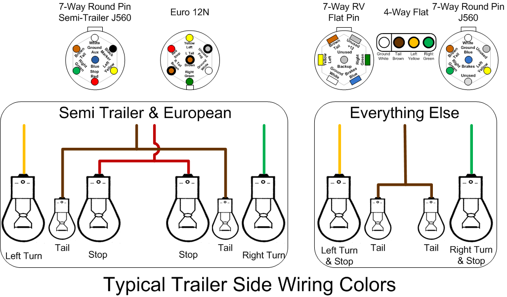
Core Powertrain and Structural Design
Connector Architecture and Pin Allocation
The SAE J560 primary connector assigns each pin a specific function, and that allocation is the core of any accurate wiring diagram. Pin 1 (white, 8 AWG) provides the ground return to the towing vehicle. Pin 2 (black) drives clearance, side marker, and identification lamps. Pin 3 (yellow) carries the left turn and hazard signal. Pin 4 (red, 10 AWG) supplies stop lamps and ABS secondary power. Pin 5 (green) carries the right turn and hazard signal. Pin 6 (brown) powers tail, license plate, and rear clearance lamps. Pin 7 (blue, 10 AWG) provides continuous ABS primary power to the trailer’s electronic control unit .
The heavier wire gauges on Pins 1, 4, and 7 reflect their higher current loads. Pin 1 must carry the return current for every illuminated lamp on the trailer simultaneously. Pins 4 and 7 supply the ABS system, which requires stable voltage to operate its wheel speed sensors and modulator valves. A voltage drop on Pin 7 below the required threshold can trigger an ABS fault code and illuminate the trailer’s exterior warning lamp, even when the ABS components themselves are functional.
It is important to distinguish the SAE J560 primary connector from the SAE J560 Auxiliary (AUX) connector. The AUX version uses a different pin 1 layout and is identified by a yellow housing or “AUX” marking; the two are not interchangeable . Auxiliary connectors supply power to lift gates, refrigeration units, or dome lamps, not to the primary lighting and ABS circuits.
Ground Circuit Integrity and Voltage Drop
The ground return is the single most important circuit in the trailer wiring system, and it is the most frequently compromised. Unlike a positive feed that powers one function, the ground pin carries the combined return current of all active circuits. When corrosion develops at Pin 1 or at the chassis ground connection, resistance increases, and the voltage available to every lamp and module drops.
A continuity test will not reliably detect this condition. A circuit with only a fraction of its copper strands intact can pass a low-current continuity check while failing under the 10 to 30 amps that lighting circuits draw in service. The definitive test is voltage drop measurement under load. Ground-side voltage drops are more common than positive-side drops because chassis paint, corrosion, and loose fasteners at the ground strap introduce resistance that is invisible to a visual inspection.
Harness Routing and Strain Relief
The wiring harness between the nose box and the trailer chassis experiences the most flex and mechanical stress of any section in the system. The coiled cord that connects the tractor to the trailer is cycled open at every uncoupling, stored facing the weather, and subjected to vibration throughout every trip. A failed strain relief at the connector entry point allows the conductors to flex at the terminals, breaking individual strands inside intact insulation. The result is the classic intermittent fault that appears when the cord is wiggled or when the vehicle hits a bump—a fault that static inspection cannot find.
Harness routing along the trailer frame must avoid suspension articulation points, sharp edges, and areas where road debris accumulates. Chafed insulation allows moisture to reach the conductors, initiating the corrosion process that eventually produces an open circuit.
Technical Specifications
The table below presents the SAE J560 primary connector pin allocation as defined by the standard. Wire gauges reflect the minimum cross-sections specified for 12-volt operation .
Comparative Advantages TCO and ROI
The alternative to systematic plug diagnosis is component substitution—replacing lamps, connectors, or harness sections based on symptoms rather than measurements. This approach appears to save diagnostic labor, but it produces repeat failures when the root cause remains unaddressed. A technician who replaces a dim tail lamp without checking the ground circuit will see the new lamp perform identically, because the fault was never in the lamp.
The cost difference is measurable. A scheduled connector maintenance program—cleaning pins, applying dielectric grease, and verifying voltage drop at each PM interval—takes approximately 10 to 15 minutes per trailer. A single misdiagnosed ground fault that generates two repeat service visits consumes several hours of technician time plus the administrative cost of the comeback. For a fleet of 40 trailers performing this maintenance twice annually, the labor investment is roughly 20 technician-hours per year. The avoided cost of even a handful of repeat electrical repairs, plus the roadside inspection failures prevented by a functioning lighting system, typically exceeds that investment within the first maintenance cycle.
Connector replacement versus pin cleaning is the other cost decision. Corrosion cleans up with contact cleaner and a brush; worn, spread, or heat-discolored pins do not. A connector with pins that are recessed below the housing face or have lost tension in the socket cannot be restored by cleaning—it requires replacement. A fleet that replaces connectors at the first sign of pin wear avoids the intermittent faults that consume diagnostic time and erode driver confidence.
Heavy Duty Application Scenarios
-
Long-haul highway fleets: The connector is cycled less frequently than in drayage operations but exposed to sustained vibration and weather. Ground pin corrosion from road spray and salt is the dominant failure mode. Scheduled cleaning at PM intervals and dielectric grease application prevent the gradual resistance buildup that produces dim or flickering lights.
-
Container drayage and port operations: High-frequency coupling and uncoupling accelerates mechanical wear on pins and strain relief. Pins that are spread or bent from rough coupling cause intermittent contact that vibration makes worse. Inspection of pin condition—not just cleanliness—is essential at every PM.
-
Cold climate operations: Temperature cycling causes expansion and contraction at connector terminals, loosening contact tension over time. Ice accumulation in the connector face can prevent full seating. Connector caps kept closed when disconnected and dielectric grease application prevent moisture ingress.
-
Fleets with mixed tractor and trailer pools: The SAE J560 standard ensures electrical compatibility, but tractor-side fuse protection and trailer-side harness condition vary independently. A trailer with a clean connector can still experience faults if the tractor’s Pin 7 supply is intermittent or the ground return through the tractor chassis is compromised.
Selection and Maintenance Considerations
Wiring diagram interpretation begins with verifying the connector standard installed on the trailer. SAE J560 and ISO 1185 are physically similar but electrically incompatible; a diagram for one will not correctly describe the other, and connecting incompatible standards can damage lamps or electronic modules . The diagram should be treated as a living document—updated when repairs modify routing or add circuits—rather than a manufacturer reference that is never consulted after delivery.
Key diagnostic and maintenance practices include:
-
Start with the ground circuit. Pin 1 carries the return current for every function. A corroded or loose ground pin produces symptoms that mimic multiple unrelated faults: dim lights, flickering markers, and ABS warnings that appear and disappear with vibration. Clean the ground pin and verify chassis ground integrity before tracing individual circuits.
-
Test by function, not by wire color. Wire colors in trailer harnesses are not reliably standardized across manufacturers. A brown wire on one trailer may be tail lamps; on another, it may serve a different function. Use a circuit tester to confirm which pin carries which signal rather than assuming color correspondence.
-
Measure voltage drop under load, not continuity. A continuity check can pass a circuit with only a fraction of its strands intact. Voltage drop testing loads the circuit and reveals the resistance that will become a failure.
-
Inspect pins for wear, not just corrosion. Pins that are worn short, recessed below the housing face, spread, or heat-discolored will not make solid contact even after cleaning. These conditions require connector or terminal replacement, not cleaning.
-
Protect the harness at flex points. The cord between the nose box and the chassis takes the most flex and pull. Flex the cord while testing continuity to reveal hidden conductor breaks that static inspection cannot find.
Conclusion
The wiring diagram for a semi trailer plug is a diagnostic instrument, not a decoration. The SAE J560 standard defines a circuit architecture in which ground integrity and pin condition determine the reliability of every downstream function. A dim marker lamp and a persistent ABS warning may share the same root cause: a corroded Pin 1 that is no longer carrying return current effectively.
Fleets that train technicians to test by function rather than wire color, measure voltage drop rather than continuity, and inspect pin condition rather than just cleanliness achieve lower electrical downtime and fewer repeat repairs. The diagram provides the map; the discipline of systematic testing provides the result. The trailer that passes its lighting check and ABS self-test on a consistent basis is not merely compliant—it is equipped with the electrical reliability that keeps it on the road and out of the repair bay.